Contact information
| Position | Research Scientist |
| Phone | +39 06 50299 249 |
| Email | |
| Office | Rome HQ |
| Address | Via di Vallerano 139, 00128 Rome, Italy |
| Research profiles | Google Scholar | Scopus | ORCID | ResearcherID | ResearchGate | Publons | CNR People |
Short biography
Sandro Ianniello is an aeronautical engineer who graduated in 1990 at the University of Rome “La Sapienza”, with a dissertation on the Numerical modelling of a acoustic feedback system devoted to the removal of flutter (coordinated by Prof. Luigi Morino). From 1992 to 2001 he worked at CIRA, the Italian Aerospace Research Centre, where he took part to a lot of European Research projects (HELINOISE, HELISHAPE, HELIFLOW, SNAAP, APIAN, EROS, ROSAA), mainly devoted to the aeroacoustic analysis of helicopter rotors and aeronautical propellers. Thus, his research was focused on the Acoustic Analogy and the numerical prediction of noise through the Ffowcs Williams and Hawkings equation. In 1997 he became the director of the Aeroacoustic Dept. at CIRA and a member of the Aeroacoustics Specialists’ Committee of CEAS (the Confederation of the European Aerospace Societies), where he was in charge until 2004. |
Research interests
| Hydroacoustics, Aeroacoustics, Computational Fluid Dynamics |
Research topics/groups
| Aeroacoustic “vs” Hydroacoustic analysis of rotating blades One of the most significant results of our recent research in hydroacoustics concerns some unexplored aspects of the behavior of rotating blades and the deep differences between the acoustic fields generated by aeronautical propellers and/or helicopter rotors in air and by marine propellers underwater. This dissimilarity does not depend either on the different fluid (air and water) or the (although existing) geometric and structural difference of the blades: it is an intrinsic feature of the generating noise mechanisms related to rotating sources and is due to the remarkable diversity of the rotational speed. A pseudo-analytic demonstration of this assertion may be achieved by analysing the integral kernels of the linear solving formulation for the Ffowcs Williams-Hawkings (FWH) equation. The analysis is based on a simple and practical approach, by introducing an elemental rotating source (named rotpole) and showing the strict similarity between its own behavior and the one of a general multibladed rotor: it shows how many assumptions and even the terminology usually adopted in Aeroacoustics (arising from decades of research strictly limited to that field) lead to relevant misunderstandings and completely wrong conclusions when applied to Hydroacoustics. The study definitely demonstrates that the underwater noise prediction from a marine propeller is an inherently nonlinear problem and, contrary to the analogous aeroacoustic problems and a rather popular belief, it requires the computation of the nonlinear quadrupole sources, just in virtue of the (very) low rotational speed. 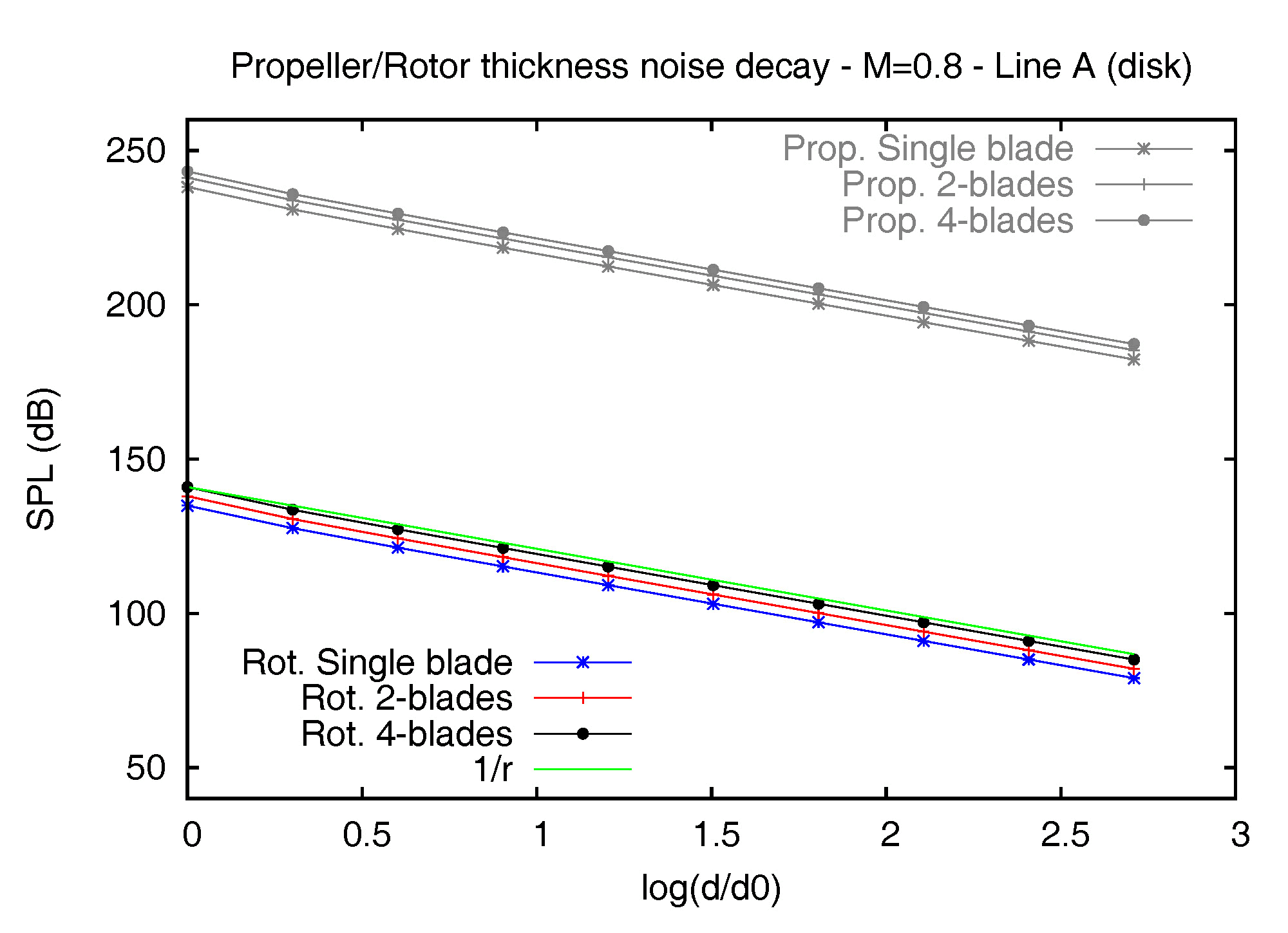
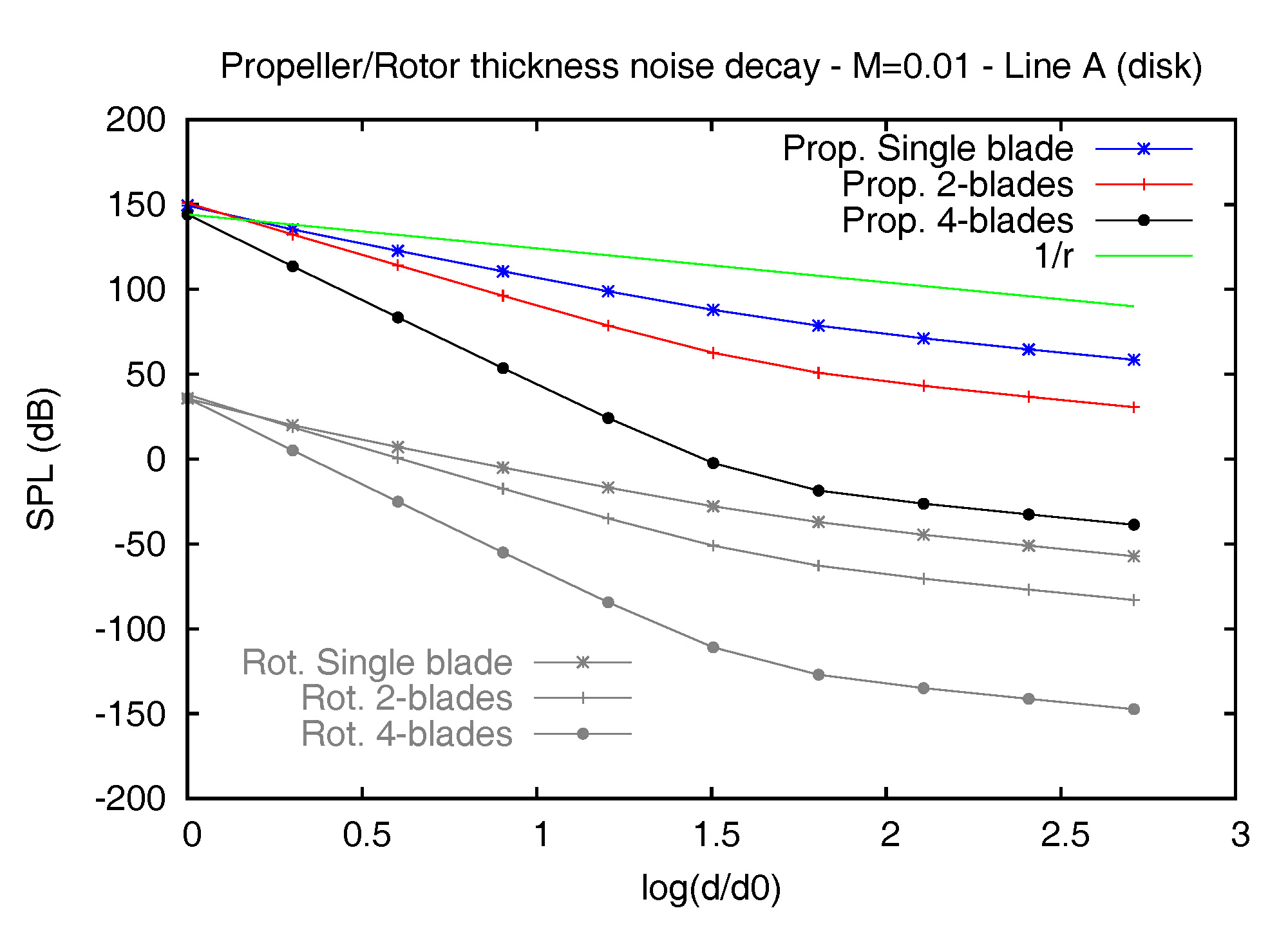
Figure 1 – Thickness noise decay of the E779A propeller and the BO-105 rotor models in the disk plane, at MR=0.8 (left) and MR=0.01 (right). The marine propeller exhibits a much higher value of the SPL, due to the very large planform with respect to the aeronautical blade (being R the same), and, above all, the same trend for all the noise decay curves. This result is meaningful. It confirms that a helicopter rotor in air and a marine propeller in water behave exactly in the same way: the shape of the body source affects the overall noise level, but the sound propagation mechanisms do not depend at all on fluid or blade’s geometry and are exclusively governed by the rotational Mach number. The acoustic equivalence of the two devices and the notable noise reduction due to the much lower MR is shown in the right picture. The thickness noise from any (single) blade rotating at MR = 0.01 decreases more rapidly in the field, following the inverse-squared law instead of the inverse one in a very extended region of the field. Furthermore, the drop of the SPL is notably increased by the mutual interactions in a multi-bladed configuration and, then, the destructive interference which occurs between the separate blades. 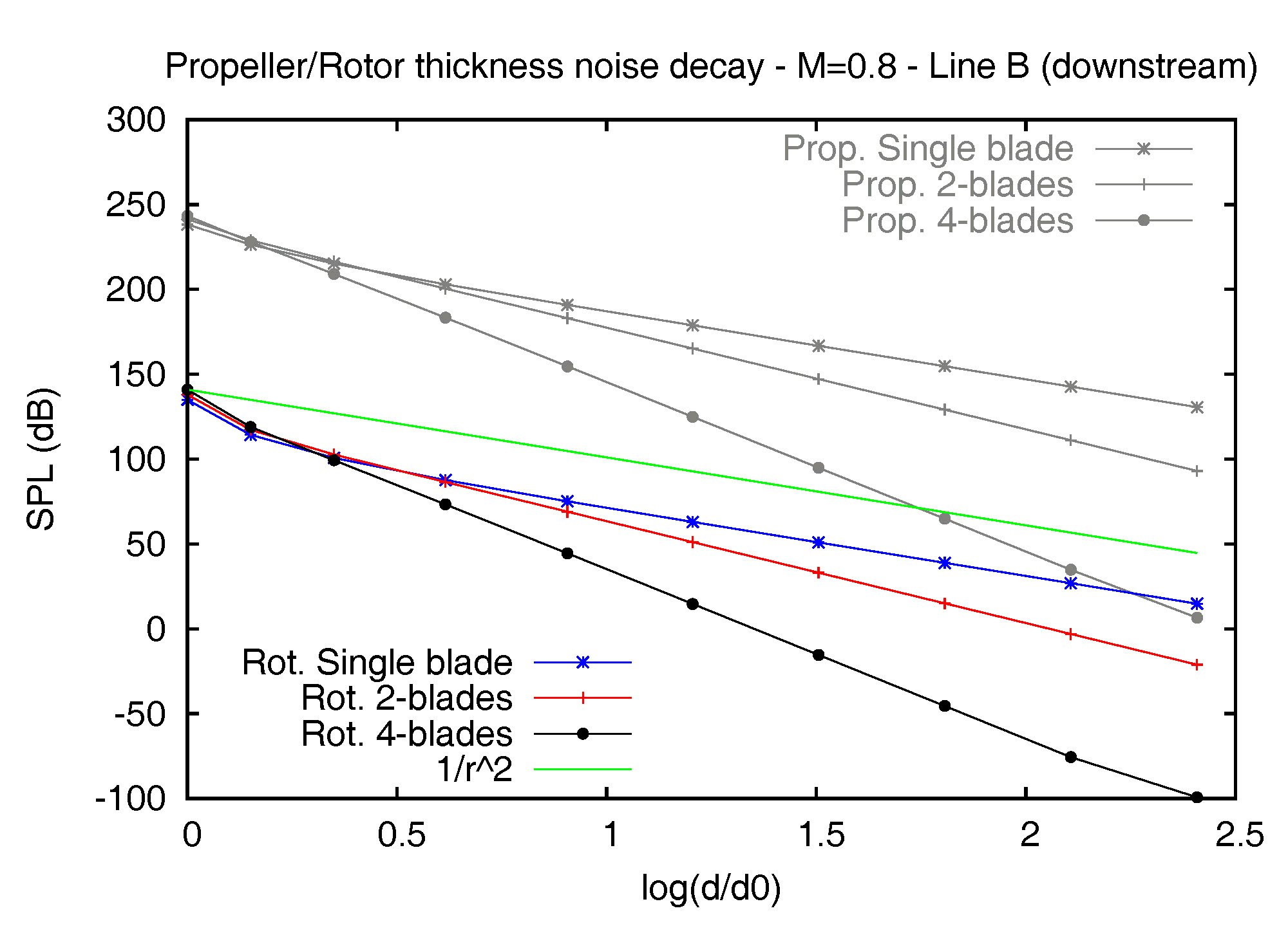
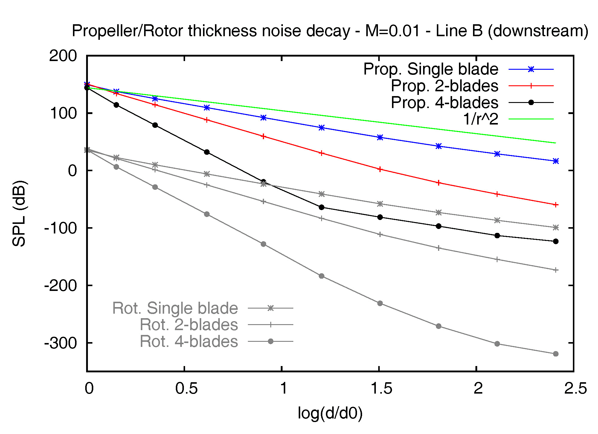
Figure 2 – Thickness noise decay of the E779A propeller and the BO-105 rotor models out of the disk plane (downstream), at MR=0.8 (left) and MR=0.01 (right). The decay curves along line B, at points located downstream the blades, are shown in figure 2, and fully confirm the intrinsic acoustic features of a rotating source/body. In this case also, in fact, the decay of the thickness term from the rotor in air soon aligns to the inverse-squared law, while the corresponding curve from the propeller underwater, at the lowest speed, shows a deeper slope (1/r3) in an extended region and gives rise to a more significant and rapid decrease of the thickness contribution. In particular, it is interesting to note the SPL values for the 4-bladed propeller at MR=0.01 along line B: at the first point, the noise level is rather high (144dB), but at only 8m from the disk plane (fourth point) it collapses to 32dB and goes to zero before the fifth point, located at only 16m from the device. The K-Algorithm Another interesting branch of our research deals with the behavior of sources rotating at supersonic speed. The issue is very important in all aeronautical applications concerning the prediction of the so-called high speed impulsive (HSI) noise, when the presence of shock waves in the flow gives rise to a loud noise of impulsive nature. The problem is related to a modification of the generating noise mechanisms (with the possible occurrence of a multi-emissive status of supersonic sources) which deeply affects the standard solving approaches for the FWH equation, making the kernels of the acoustic integrals singular. The singularity is usually expressed by the Doppler factor |1-Mr| appearing at the denominator of all integral terms, where Mr is the projection of the Mach vector in the source-observer direction. A possible solution to this problem is the adoption of an emission surface formulation, where the integration domain moves from the rotating (rigid or permeable) surface to its own retarded (time-dependent) configuration and the Doppler factor is replaced by a weaker and somehow more manageable singularity (Lambda). In this case, however, the complexity of the problem stands in the modeling of the emission surface, which in presence of supersonic sources may exhibit a very complex time evolution, characterized by topological transformations. 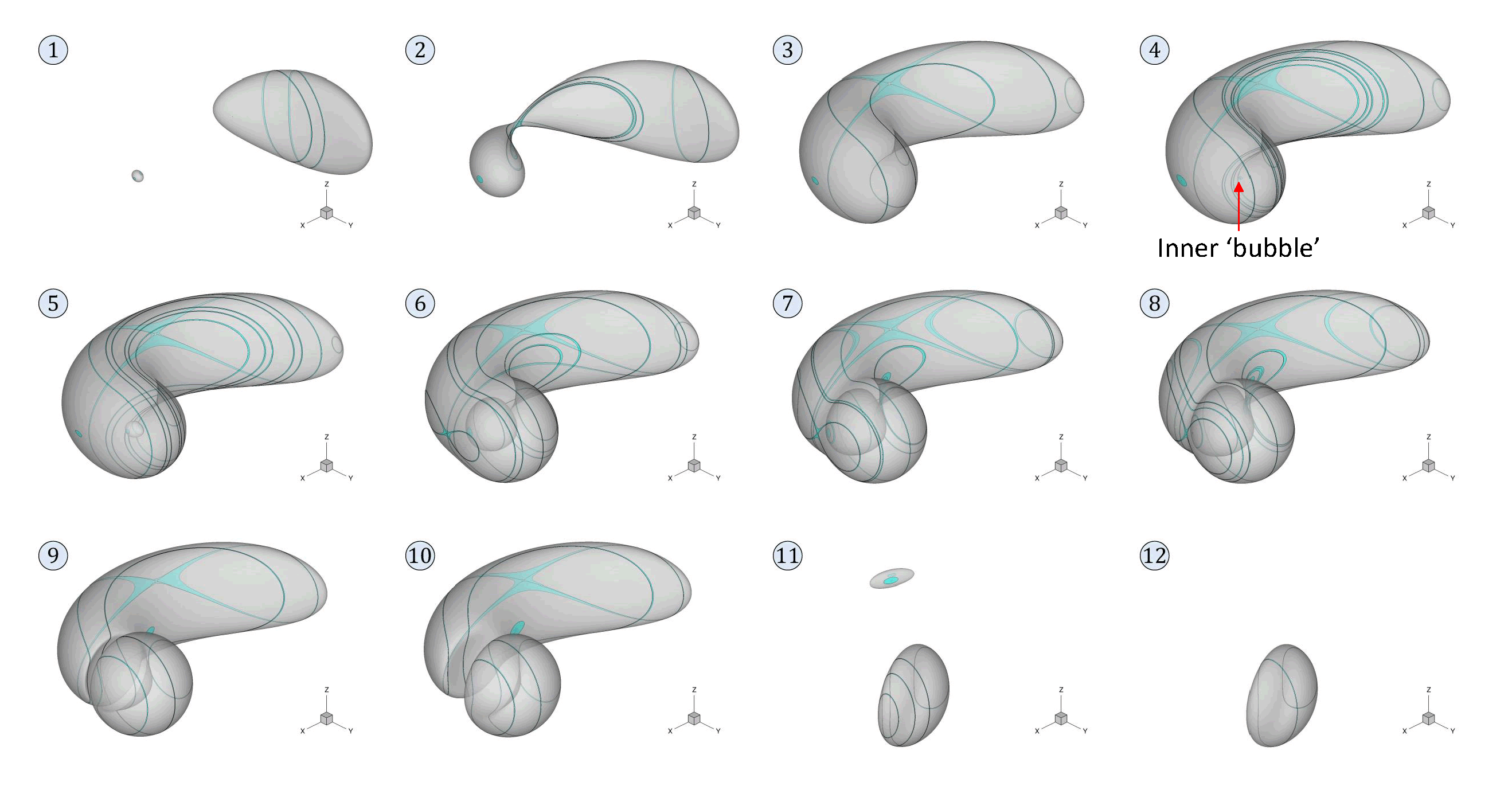
Figure 3 – Time evolution of the emission surface for a sphere rotating at MR=2.3 and an observer located along the trajectory of the same body. In order to demonstrate the K-algorithm’s effectiveness, figure 3 shows twelve subsequent retarded configurations of a sphere rotating at a tip Mach number MR=2.3 and an observer positioned along the trajectory of the body itself. The test, of course, has no physical meaning, but the unusual configurations occurring when the retarded domain “crosses” the observer represent a true challenge for the whole procedure. As expected, the early occurrence of multiple sources gives rise to a small, separate region (frame 1), which rapidly grows and joins the primary domain (frame 2); note the algorithm’s capability to model such a critical connection stage, characterized by a thin choke point. The merging of the two regions goes on and the overall area of the emission domain increases (frame 3). Nevertheless, the secondary patch soon assumes a partially spherical shape and a sort of steady-state: the whole retarded domain, in fact, does not move any longer along the circular trajectory, while a sort of inner bubble appears just in the proximity of the observer location (frame 4). From this step on, the increase of the area is almost exclusively due to the broadening of the inner patch, which always embeds the observer and exhibits a rounded, although not symmetrical, shape (frames 5-7). Frame 8 marks the peak value of the retarded domain area; this configuration gives rise to a cusp point in the time-dependent area function, which identifies the forthcoming connection between the inner bubble and the external surface. In the subsequent step, in fact, the domain looks constituted by two well-defined and separate regions, exhibiting a local, heavily concave shape (frame 9), and the global area starts to decrease. At this stage, the old primary region rapidly reduces and collapses, while a semi-spherical, concave patch resumes the rotation, progressively comes back to a convex shape and leaves the multi-emissive status definitely (frames 10-12). 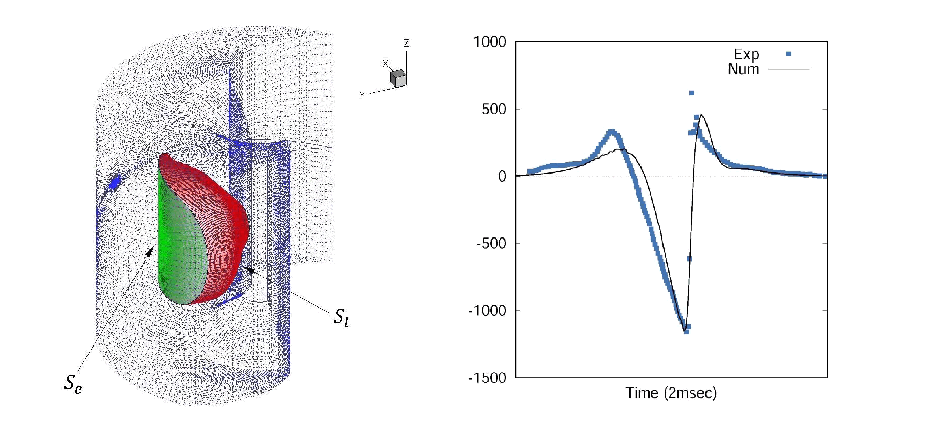
Figure 4 – Noise prediction for the UH-1H non-lifting hovering blade at MR=0.95, as achieved by coupling the K-Algorithm with the porous formulation. Concerning the actual noise prediction, figure 4 shows the result achieved in the classic test of the isolated blade of the UH-1H non-lifting hovering rotor at MR=0.95, with an observer located in the disk plane at 3.09R from the hub (being R the rotor radius). In this case, the shock delocalization phenomena dictates the accounting for supersonic sources. The noise is computed by coupling the K-Algorithm with the porous formulation, by exploiting the availability of fluid dynamic data provide by an Euler code. The left picture depicts the adopted integration domain (here split into lateral- and end-surfaces) as extracted from the Euler mesh, while the right picture shows the excellent agreement between the available experimental data and the numerical result, here able to “capture” both the negative peak value and the typical asymmetrical waveform of the pressure signature, induced by the shock. |
Selected projects
| SILENV (Ships oriented Innovative solutions to rEduce Noise & Vibrations) |
The SILENV project (2009-2012) was the first research programme financed by the European Community focused on acoustic themes in naval context. It arose from the need to solve or alleviate the many problems caused by noise and vibrations on maritime transport, with particular reference to noise pollution and its effects on marine fauna and port areas, to safeguarding the health of crews and to passengers’ comfort on board. Therefore, starting from a study and a collection of the current regulations on the subject, the research was addressed to different sectors, in order to propose and test innovative solutions and to define a “Green Label” identifying (on the basis of the characteristics of the current fleets) new regulatory targets for noise and vibration levels in new generation ships. The work was divided into 5 primary work packages (WPs), which a management WP (the WP0, by the coordinator) and a WP of dissemination (WP6, dedicated to the organization of a website, special workshops and seminars within the project, participation in congresses, publication of articles and other) were added to. |
Selected publications
- M. Cianferra, S. Ianniello, V. Armenio, Assessment of methodologies for the solution of the Ffowcs Williams and Hawkings equation using LES of incompressible single-phase flow around a finite-size square cylinder, Journal of Sound & Vibration, 2019, in press
- C. Testa, S. Ianniello, F. Salvatore, A Ffowcs Williams and Hawkings formulation for hydroacoustic analysis of propeller sheet cavitation, Journal of Sound & Vibration, 413, 2018, pp. 421-441
- M. Cianferra, V. Armenio, S. Ianniello, Hydroacoustic noise from different geometries, International Journal of Heat and Fluid Flow, 70, 2018, pp. 348-362
- S. Ianniello, The Ffowcs Williams-Hawkings equation for hydroacoustic analysis of rotating blades. Part 1. The rotpole, Journal of Fluid Mechanics, 797, 2016, pp. 345-388
- S. Ianniello, E. De Bernardis, Farassat’s formulations in marine propeller hydroacoustics, International Journal of Aeroacoustics, 14 (1-2), 2015, pp. 87-103
- S. Ianniello, R. Muscari, A. Di Mascio, Ship underwater noise assessment by the Acoustic Analogy. Part III: measurements versus numerical predictions, Journal of Marine Science & Technology, 19 (2) , 2014, pp. 125-142
- S. Ianniello, R. Muscari, A. Di Mascio, Ship underwater noise assessment by the Acoustic Analogy. Part II: hydroacoustic analysis of a ship scaled model, Journal of Marine Science & Technology, 19 (1) , 2014, pp. 52-74
- S. Ianniello, R. Muscari, A. Di Mascio, Ship underwater noise assessment by the Acoustic Analogy. Part I: nonlinear analysis of a marine propeller in a uniform flow, Journal of Marine Science & Technology, 18 (4) , 2013, pp. 547-570
- S. Ianniello, A. Di Mascio, A self-adaptive oriented particles Level-Set method for tracking interfaces, Journal of Computational Physics, 229, 2010, pp. 1353-1380
- C. Testa, S. Ianniello, F. Salvatore, M. Gennaretti, Numerical approaches for hydroacoustic analysis of marine propellers, Journal of Ship Research, 52 (1), 2008, pp.57-70
- S. Ianniello, New perspectives in the use of the Ffowcs Williams-Hawkings equation for aeroacoustic analysis of rotating blades, Journal of Fluid Mechanics, 570, 2007, pp. 79-127
- F. Salvatore, S. Ianniello, Preliminary results on acoustic modelling of cavitating propellers, Computational Mechanics, 32, 2003, pp. 291-300
- S. Ianniello, Aeroacoustic analysis of high tip speed rotating blades, Journal of Aerospace & Technology, 5 (3), 2001, pp. 179-192
- S. Ianniello, Quadrupole noise predictions through the Ffowcs Williams-Hawkings equation, AIAA Journal, 37 (6), 1999, pp. 1048-1054
- S. Ianniello, Algorithm to integrate the Ffowcs Williams-Hawkings equation on supersonic rotating domain, AIAA Journal, 37 (6), 1999, pp. 1040-1047